Applications of the Superluminescent Diode (SLD)
InPhenix, Inc.,
250 N. Mines Road, Livermore, CA 94551, USA


 2.3 Fiber-Optic Link Testing
SLDs are used in the diagnostics of optical fiber communication networks in the 1310nm and 1550nm bands. The chromatic dispersion of an optical medium is the phenomenon that the phase velocity and group velocity of light propagating in a transparent medium depend on the optical frequency. Dispersion has an important impact on the propagation of optical pulses, because a pulse always has a finite spectral width (bandwidth), so that dispersion can cause its frequency components to propagate with different velocities. Normal dispersion, for example, leads to a lower group velocity of higher-frequency components, and thus to a positive chirp, whereas anomalous dispersion creates negative chirps. The frequency dependence of the group velocity also has an effect on the pulse duration. If the pulse is initially unchirped, dispersion in a medium will always increase its duration (dispersive pulse broadening).
In optical fibers, there is usually some slight difference in the propagation characteristics of light waves with different polarization states. This is called polarization mode dispersion (PMD) [3]. A differential group delay can occur even for fibers that according to the design should have a rotational symmetry and thus exhibit no birefringence. This effect can result from random imperfections or bending of the fibers, or from other kinds of mechanical stress, and is also affected by temperature changes. Mainly due to the influence of bending, the PMD of a cabled fiber can be completely different from that of the same fiber on a spool. Modern fiber cables as used in fiber-optic links have been optimized for low PMD, but the handling of such cables can still have some influence. PMD can have adverse effects on optical data transmission in fiber-optic links over long distances at very high data rates, because portions of the transmitted signals in different polarization modes will arrive at slightly different times. Effectively, this can cause some level of pulse broadening, leading to inter-symbol interference, and thus a degradation of the received signal, leading to an increased bit error rate.
The chromatic dispersion and polarization mode dispersion (PMD) can be measured by using the large bandwidth, high power spectral density, and low ripple characteristics of SLDs.
2.4 WDM PON Systems
The Wavelength Division Multiplexing (WDM) Passive Optical Networks (PON) has been used and developed as one of the approaches for Fiber To The Home (FTTH) network systems [5][6]. As a low-cost laser source at the Optical Network Unit (ONU) in such WDM PON systems, the Fabry Perot (FP) laser diode (LD) wavelength is locked to a selected wavelength channel of the broad-band Amplified Spontaneous Emission (ASE) source.[6]. Fig. 4 shows an architecture for upstream transmission employing wavelength-locked FP LDs [6]. A broad-band ASE source (such as SLD) with an optical circulator is located at the central office. The broadband ASE is transmitted to the remote node where an Arrayed Waveguide Grating (AWG) slices the ASE spectrally. The spectrally sliced ASE is injected into the FP LD located at the ONU.

Fig. 4 WDM PON System Upstream Configuration
2.5 Fiber-Optic Sensors (FOS) ( a ) Advantages of FOS Small size No electrical power is needed at the remote location Many sensors can be multiplexed along the length of a fiber by using different wavelengths of light for each sensor, by sensing the time delay as light passes along the fiber through each sensor. ( b ) Types of FOS There are two types of fiber optic sensors: Intrisic sensors: Optical fiber itself is used as the sensing element. Extrinsic sensors: Optical fiber is used as a means of relaying signals from a remote sensor to the electronics that process the signals. ( c ) Intrinsic Sensors Fiber-Optic Strain, Temperature, and Pressure sensors The optical characteristics of an optical fiber is sensitive to the strain, temperature, and pressure, which modulates the intensity, phase, polarization, wavelength, or transit time of light in the fiber. A particularly useful feature of intrinsic fiber optic sensors is that they can, if required, provide distributed sensing over very large distances. Optical fiber sensors for temperature and pressure have been developed for downhole measurement in oil wells. The fiber optic sensor is best suited for this environment as it functions at temperatures too high for semiconductor sensors (distributed temperature sensing). Fiber-optic sensors have been developed to measure co-located temperature and strain simultaneously with very high accuracy using fiber Bragg gratings. This is particularly useful when acquiring information from small complex structures. Brillouin scattering effects can be used to detect strain and temperature over larger distances (20–30 kilometers). The fiber sensor is especially useful for harsh environment. Example: Bragg grating sensors for strain and temperature A schematic diagram of the fiber Bragg grating sensor is shown in Fig. 5. The Bragg wavelength can be expressed as,where $n$ is the mode index of the fiber, and $\Lambda$ is the grating period. Equation (1) gives,
where $\Delta\lambda_B$, $\Delta n$ and $\Delta\Lambda$ express a small change of $\lambda_B$, $n$, and $\Lambda$, respectively.

where $\varphi_S$ is the so called Sagnac phase shift, and
where $\sigma$ is the photodetector responsivity and $P$ is the power coupled into the input fiber[cite: 4].
The Sagnac phase shift $\varphi_S$ is given by (see Fig. 7)[cite: 4],
where
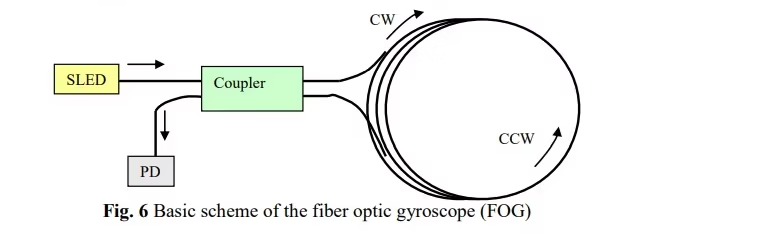
Fig. 6 Basic scheme of the fiber optic gyroscope (FOG)[cite: 4]
