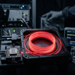
Distributed Feedback (DFB Lasers) serve as the backbone of modern optical communications, high-speed data center interconnects, and precision sensing systems. Because of their stable single longitudinal mode operation, single-frequency operation, and narrow spectral linewidth, they are the preferred light source for high-capacity fiber optic networks. However, when engineers deploy DFB Lasers in directly modulated configurations, managing wavelength chirp remains one of the most critical challenges to overcome.
Wavelength chirp—the undesired frequency shift that occurs during direct current modulation—broadens the optical spectrum. This spectral broadening interacts unfavorably with chromatic dispersion in optical fibers, leading to signal degradation, pulse broadening, and transmission penalties over long distances. Mastering how to control chirp is essential for maintaining signal integrity in high-bit-rate transmission systems.
This comprehensive guide explores the physics of dynamic chirp and outlines five critical tips for controlling wavelength chirp in directly modulated DFB Lasers, while highlighting how advanced engineering and robust manufacturing from industry leaders like Inphenix ensure superior optical performance.
Understanding the Roots of Wavelength Chirp in DFB Lasers
Before diving into mitigation strategies, it is important to understand why chirp happens. In a semiconductor laser diode, direct modulation is achieved by varying the injection current directly into the active region. This fluctuation in injection current causes two simultaneous changes inside the cavity:
- Carrier Density Variations: Changes in the carrier injection alter the refractive index of the semiconductor material through the linewidth enhancement factor (alpha factor).
- Thermal Variations: Dissipated power changes the local temperature of the laser chip, altering the optical path length and refractive index over longer time scales.
These combined effects, along with the laser equipment characteristics, result in transient and adiabatic chirp. Transient chirp occurs rapidly during the rising and falling edges of a data pulse, while adiabatic chirp correlates directly with the instantaneous power level. Left unmanaged, chirp limits the reach and transmission capacity of systems utilizing DFB Lasers.
To combat these limitations, system designers must optimize both the electrical driving circuitry and the optical component selection. Below are five actionable tips to minimize wavelength chirp and optimize your optical link performance.
Tip 1: Optimize Bias Current and Modulation Amplitude Settings
The operating point of your DFB Lasers dictates how severely the refractive index fluctuates under modulation. Operating too close to the threshold current drastically increases the alpha factor impact and exacerbates transient chirp.
- Maintain a High DC Bias: Ensure the DC pre-bias current is set well above the threshold current level. A higher bias current dampens carrier density fluctuations relative to the optical power swing.
- Balance Modulation Depth: Avoid driving the laser into deep depletion or heavy compression zones. Over-driving the modulation current accelerates carrier density swings, immediately worsening frequency chirp.
- Leverage Pre-Characterized Components: When sourcing hardware, utilize devices with well-documented current-versus-power curves. High-performance Inphenix DFB Lasers provide stable threshold profiles and low alpha factors, making them exceptionally well-suited for direct modulation schemes where bias optimization and appropriate equipment selection are crucial, demonstrating significant innovation in laser technology.
Tip 2: Implement Advanced Thermal Management and TEC Control
Thermal chirp is a slower, cumulative phenomenon caused by joule heating during active modulation. As current pulses heat up the active region, the Bragg wavelength shifts toward longer wavelengths (redshift).
- Integrate Robust TECs: Always choose DFB Lasers equipped with high-efficiency Thermoelectric Coolers (TECs) and precision thermistors. Continuous closed-loop thermal regulation stabilizes the operating temperature of the chip.
- Minimize Thermal Impedance: Ensure your mounting and packaging design provides low thermal resistance paths to dissipate heat away from the laser submount.
- Monitor Ambient Stability: Even with active cooling, sudden ambient temperature shifts can introduce thermal gradients across the laser facet, introducing unwanted adiabatic chirp components into your transmission stream.
Tip 3: Tailor the External Electrical Drive Circuitry
The shape, rise time, and fall time of the electrical driving pulse play a massive role in how severely a single longitudinal mode semiconductor laser chirps during operation, and utilizing a diffraction grating can aid in analyzing and managing these effects. Sharp, unfiltered electrical edges induce severe ringing and massive transient chirp spikes.
- Use Pulse Shaping Techniques: Implement low-pass filtering or pulse-shaping networks in your laser driver circuit to smooth out extremely sharp edges of high-speed data pulses.
- Impedance Matching: Ensure tight 50-ohm impedance matching between the driver circuit and the DFB Lasers packaging (such as butterfly or TO-can configurations). Mismatches cause electrical reflections that distort the modulation current.
- Minimize Parasitic Capacitance: Wire bonds and packaging leads introduce parasitic inductance and capacitance. Advanced packaging reduces these parasitics, ensuring that the actual current reaching the active region matches the designed drive signal without introducing secondary electrical resonances.
Tip 4: Select Devices with Low Linewidth Enhancement Factors ($\alpha$-factor)
The linewidth enhancement factor is a fundamental material property of the semiconductor active region that couples carrier-induced refractive index changes to gain variations. A lower $\alpha$-factor inherently results in lower wavelength chirp.
- Evaluate Active Region Materials: Multi-quantum well (MQW) structures can be engineered with specific strain profiles to suppress the linewidth enhancement factor, promoting operation in a single longitudinal mode.
- Review Vendor Specifications: When evaluating component datasheets, pay close attention to parameters linked to dynamic spectral width under modulation. Sourcing from manufacturers who specialize in advanced optoelectronics guarantees tighter control over material composition. For custom wavelengths and low-chirp semiconductor profiles, exploring comprehensive options via Inphenix Products ensures your design utilizes state-of-the-art chip architectures.
- Consider Alternative Modulations When Necessary: If your transmission distance or bit rate exceeds the physical limits of directly modulated DFB Lasers, consider utilizing an external modulator configuration, though optimizing the direct modulation parameters remains the most cost-effective first step.
Tip 5: Utilize Optical Filtering and Dispersion Compensation
If your system architecture requires high-speed transmission where some level of chirp is unavoidable, system-level mitigation techniques can neutralize the penalty caused by fiber chromatic dispersion.
- Employ Optical Bandpass Filters: Passing a chirped signal through a narrow optical bandpass filter can convert frequency modulation (chirp) into amplitude modulation, effectively suppressing the unwanted wing components of the spectrum.
- Deploy Dispersion Compensation Fiber (DCF): In legacy or long-haul fiber spans, employing a diffraction grating along with matching positive chirp from DFB Lasers with negative dispersion fiber (or vice versa) can actually help compress pulses under specific conditions.
- System Margin Budgeting: Always factor residual chirp penalty into your link power budget during the initial design phase, ensuring your receiver retains sufficient sensitivity even after fiber propagation.
Engineering Superior Optical Systems with DFB Lasers
Controlling wavelength chirp in directly modulated DFB Lasers is a multi-faceted engineering challenge that spans electrical driver design, thermal management, and component selection. By systematically optimizing your bias parameters, implementing rigorous thermal controls, smoothing driver electrical edges, and selecting high-purity semiconductor components, you can drastically reduce spectral broadening and achieve reliable, long-distance transmission performance.
As optical networks and sensing architectures push toward higher speeds and tighter tolerances, partnering with an experienced manufacturer fosters innovation and makes all the difference. Building your next-generation hardware with world-class components guarantees the stability, low linewidth, and low-chirp performance required to stay ahead.
Elevate Your Optical Performance Today
Are you ready to integrate high-reliability, low-chirp optical sources into your next engineering project? Discover the complete portfolio of advanced semiconductor components, including high-performance DFB Lasers and custom optical solutions, by visiting Inphenix. Contact the Inphenix engineering team today to discuss your exact custom wavelength requirements, request data sheets, or find the ideal light source for your application.