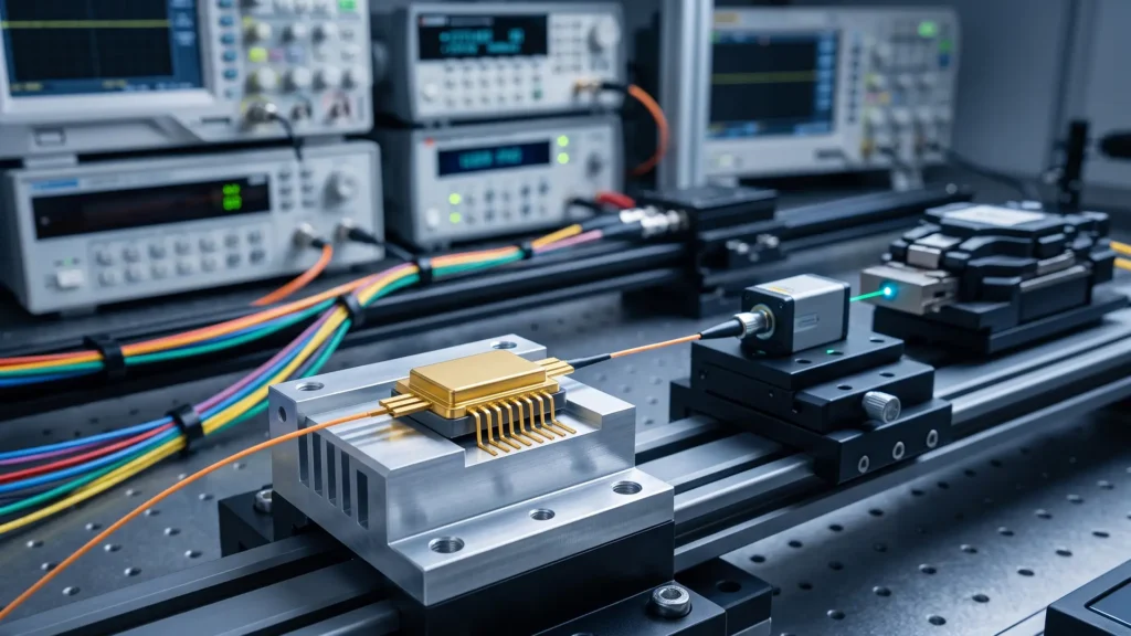
Navigating the complex specifications of optical components is a daily reality for modern systems engineers. Whether you are designing next-generation telecommunications infrastructure, high-resolution LiDAR systems, or precision gas sensing equipment, selecting the right light source dictates the performance ceiling of your entire architecture. At the heart of many of these advanced systems is the DFB laser.
Understanding how to read and interpret a DFB laser data sheet is critical to ensuring your system meets its performance, thermal, and budgetary targets. A DFB laser, or Distributed Feedback laser, utilizes a diffraction grating built directly into the active region of the semiconductor, allowing it to emit a single, highly stable longitudinal mode. This unique structure provides exceptional wavelength stability and narrow linewidth, but it also means the data sheet contains specific metrics that differ from standard Fabry-Perot laser diodes.
This comprehensive guide breaks down the essential parameters found in a standard DFB laser data sheet, helping you map distributed feedback laser specifications directly to your system requirements.
1. Absolute Maximum Ratings: The Survival Thresholds
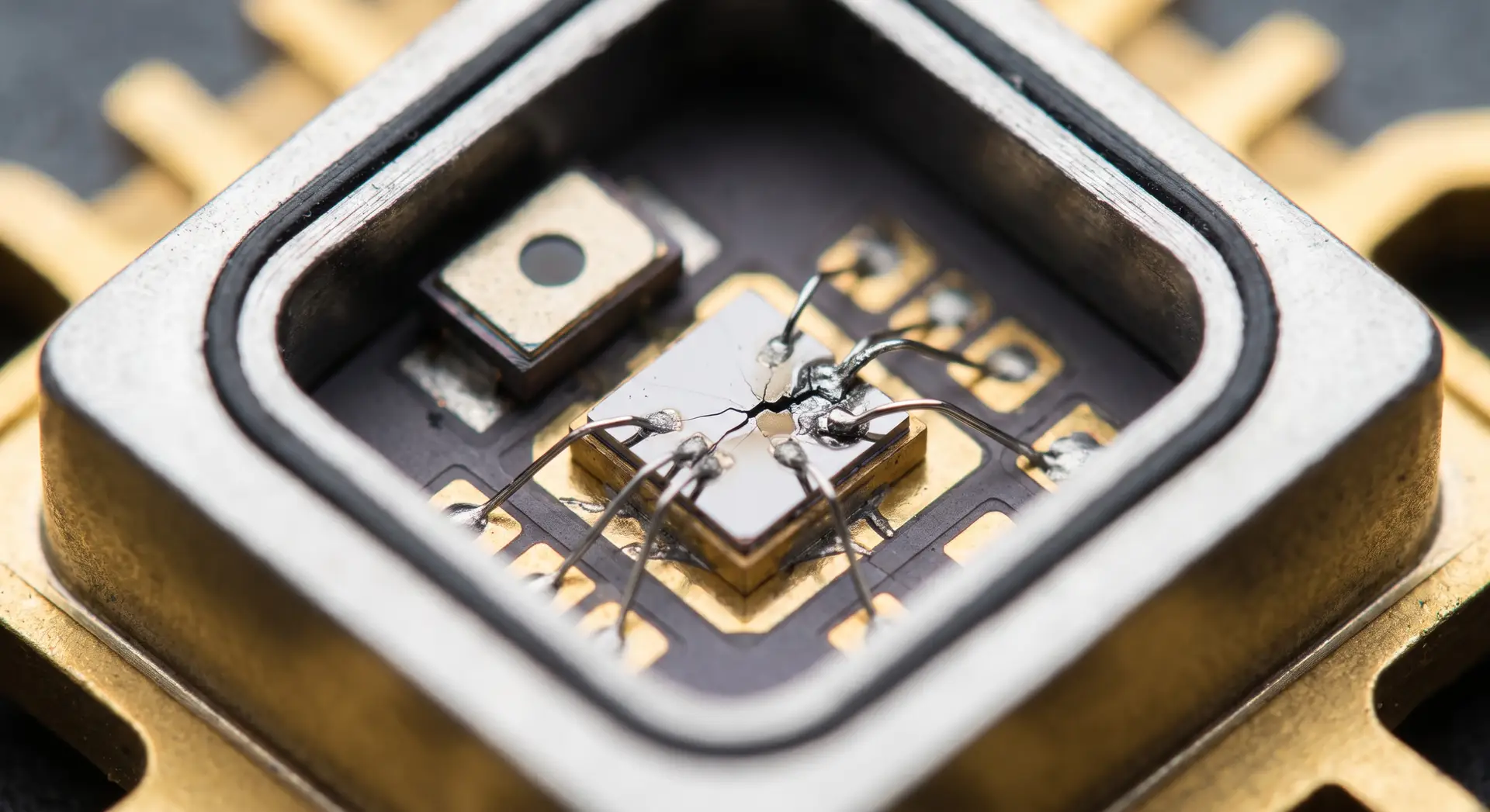
Before diving into performance metrics, systems engineers must review the Absolute Maximum Ratings. These are the stress limits of the DFB laser. Exceeding these parameters, even for a microsecond, can lead to catastrophic optical damage (COD), facet degradation, or immediate device failure.
- Forward Current (I_f): The absolute maximum electrical current you can safely drive through the DFB laser diode. Operating near this limit drastically reduces the lifespan of the component.
- Reverse Voltage (V_r): DFB lasers are highly sensitive to reverse bias. This parameter is typically very low (often around 2V). Systems must be designed with proper transient protection to prevent reverse voltage spikes.
- Operating Temperature Range: The ambient or case temperature range within which the DFB laser can function without sustaining physical damage. Note that operating at the extremes of this range will significantly alter optical characteristics.
- Storage Temperature: The safe temperature range for the DFB laser when unpowered.
2. Optical Characteristics: Defining the Light
The optical specifications are the core of any DFB laser data sheet, and understanding the use of manufacturing processes and category cables like cat6 in these setups can be critical for ensuring seamless data transmission. They determine the quality, intensity, and purity of the light emitted, which directly impacts signal integrity in fiber optic communication systems and accuracy in metrology applications.
Center Wavelength (λ_c)
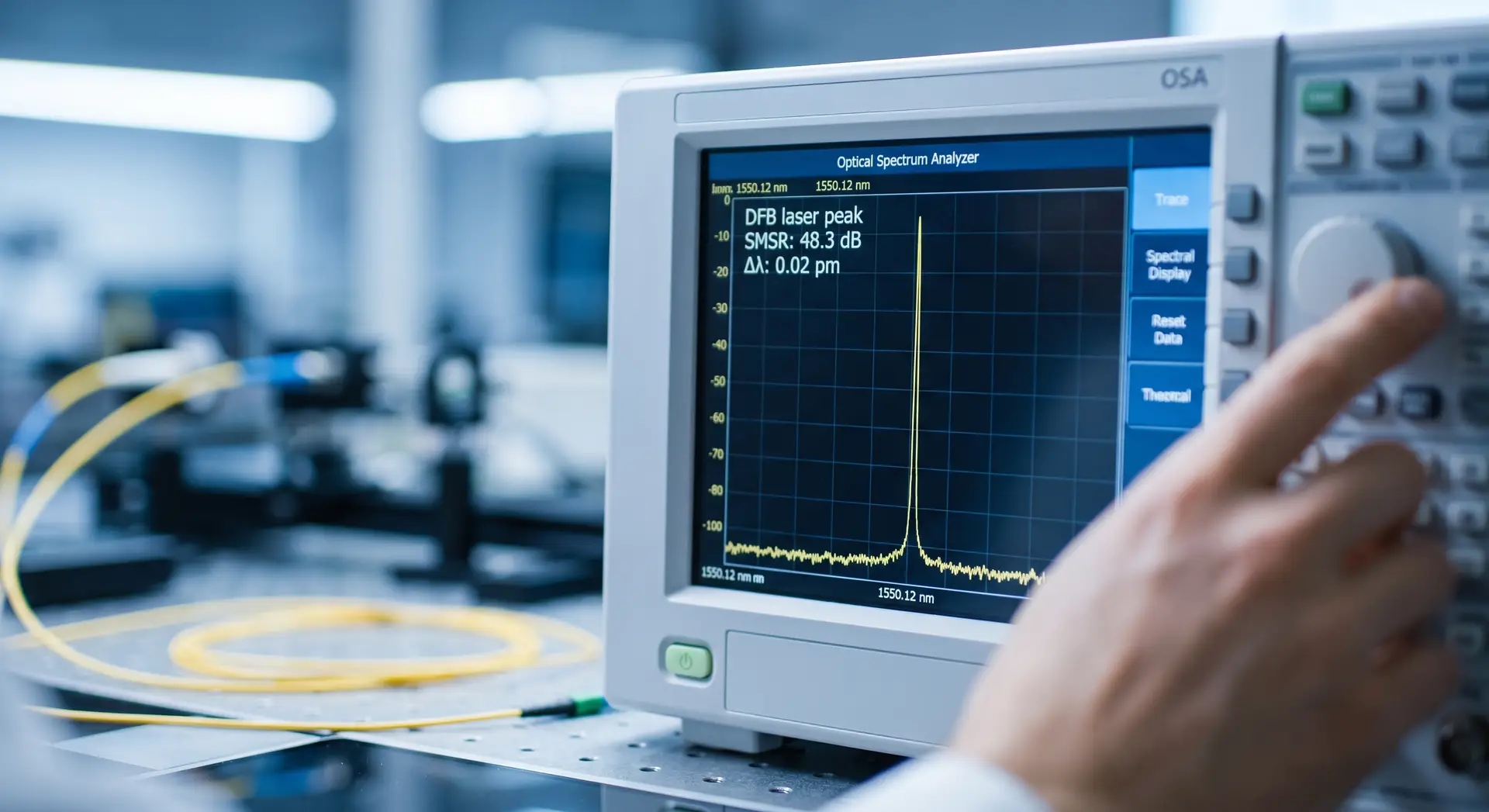
The center wavelength is the primary specification for any DFB laser. Due to the built-in Bragg grating, a DFB laser is designed to emit at a very specific wavelength (e.g., 1310 nm, 1550 nm, or specific ITU grid channels). The data sheet will provide a typical center wavelength along with a tolerance range (minimum and maximum). For Dense Wavelength Division Multiplexing (DWDM) applications, selecting a DFB laser with a tightly toleranced center wavelength is non-negotiable.
Side Mode Suppression Ratio (SMSR)
Because a DFB laser is designed for single-frequency operation, the SMSR is a critical indicator of spectral purity. It measures the power difference between the primary emission peak (the main mode) and the next highest secondary peak (the side mode), expressed in decibels (dB).
- Systems Engineering Impact: A high SMSR (typically >40 dB for a high-quality DFB laser) ensures that almost all the optical power is concentrated in the desired wavelength. Low SMSR can lead to modal noise and chromatic dispersion penalties over long fiber spans.
Spectral Linewidth (Δλ or Δν)
Unlike standard laser diodes that emit over a broad spectrum, a DFB laser produces a remarkably narrow linewidth. The data sheet may express this in picometers (pm) or Megahertz (MHz).
- Systems Engineering Impact: For coherent communications or acoustic sensing, the linewidth of the DFB laser dictates the coherence length and the phase noise of the system. A narrower linewidth translates to higher resolution in sensors and longer transmission distances without signal degradation.
Optical Output Power (P_out)
This indicates the typical optical power emitted from the facet or the coupled fiber, measured in milliwatts (mW) or dBm. Data sheets usually specify a nominal operating power and a maximum rated output power. When integrating a DFB laser, engineers must account for insertion losses from subsequent optical isolators, modulators, or multiplexers to ensure the final output meets the link budget.
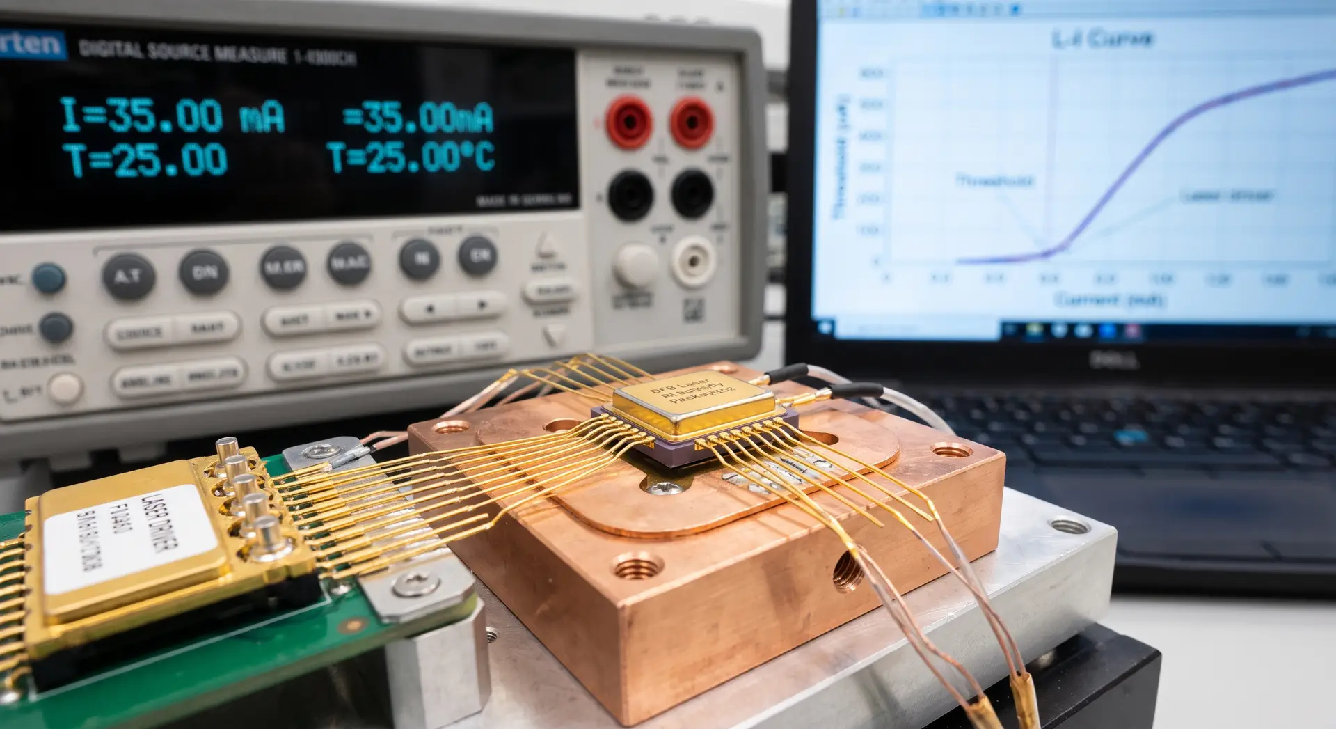
3. Electrical and Tuning Parameters: Driving the Device
A DFB laser requires precise electrical control and innovation to maintain its single-frequency stability. The electrical parameters guide the design of your laser driver and thermal control circuits.
Threshold Current (I_th)
The threshold current is the minimum electrical current required for the DFB laser to achieve stimulated emission and begin lasing. Below this point, the device acts merely as a Light Emitting Diode (LED). Systems Engineering Impact: A lower threshold current is generally desirable, as it indicates a more efficient DFB laser that generates less waste heat. Threshold current increases exponentially with temperature, making proper thermal management critical.
Operating Current (I_op) and Forward Voltage (V_f)
These parameters specify the electrical conditions required to achieve the nominal optical output power. The product of I_op and V_f determines the electrical power consumed by the DFB laser, allowing systems engineers to calculate the thermal dissipation requirements for the surrounding heatsink or cooling system.
Slope Efficiency (η)
Expressed in milliwatts per milliamp (mW/mA), slope efficiency defines how effectively the DFB laser converts additional electrical current into optical power once it has surpassed the threshold current. A highly efficient DFB laser requires a less demanding driver circuit, which can simplify system design and reduce overall power consumption.
Wavelength Tuning Coefficients
One of the most powerful features of a DFB laser is its tunability. While it emits a single frequency, that frequency can be finely adjusted to lock onto specific absorption lines or optical channels.
- Temperature Tuning Coefficient (Δλ/ΔT): Indicates how the center wavelength shifts with changes in the diode’s temperature, typically around 0.1 nm/°C for a 1550 nm DFB laser. Systems engineers use integrated Thermoelectric Coolers (TECs) to exploit this coefficient for precise wavelength stabilization.
- Current Tuning Coefficient (Δλ/ΔI): Indicates how the wavelength shifts in response to changes in the drive current. This is usually a much smaller shift than temperature tuning but happens instantaneously, allowing for rapid frequency modulation (FM) in chirp-based applications.
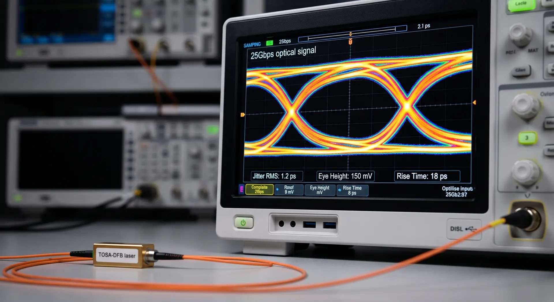
4. High-Speed and Modulation Characteristics
When a DFB laser is used for data transmission or rapid scanning, its dynamic characteristics become just as important as its static optical properties.
Modulation Bandwidth (f_3dB)
This parameter defines the maximum frequency at which the DFB laser, often utilizing cat6 infrastructure, can be directly modulated while still maintaining adequate signal integrity. If your system requires transmitting data at 10 Gbps or 25 Gbps, you must verify that the DFB laser bandwidth supports these speeds without suffering from severe inter-symbol interference (ISI).
Relative Intensity Noise (RIN)
RIN is a measure of the fluctuations in the optical power output of the DFB laser, expressed in dB/Hz. In analog RF-over-fiber applications or high-order QAM digital transmission, a high RIN will raise the noise floor and degrade the Signal-to-Noise Ratio (SNR). A premium DFB laser will typically feature a RIN of -145 dB/Hz or better.
Laser Chirp
When a DFB laser is directly modulated by varying the drive current, the carrier density in the active region fluctuates. This fluctuation changes the refractive index, causing a transient shift in the emission wavelength known as chirp. While acceptable in short-reach networks, excessive chirp interacting with chromatic dispersion in long-haul networks leads to severe signal distortion. For long-haul systems, engineers often operate the DFB laser continuously (Continuous Wave or CW mode) and use an external modulator (like a Mach-Zehnder Modulator) to avoid chirp.
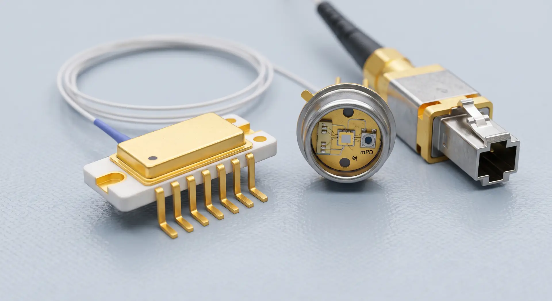
5. Packaging and Integrated Components
The physical format of the DFB laser is crucial for mechanical integration and environmental stability. Data sheets will outline the package type and the integrated components that accompany the raw laser chip.
Package Types
- Butterfly Package (14-pin or 7-pin): The industry standard for telecom and high-performance DFB laser applications. It typically includes the laser diode, a thermistor, a TEC, and a monitor photodiode inside a hermetically sealed, fiber-coupled housing.
- TO-Can (e.g., TO-56): A smaller, cylindrical package often used for cost-sensitive or space-constrained DFB laser applications. They may or may not include integrated cooling.
- TOSA (Transmitter Optical Sub-Assembly): A packaged DFB laser designed specifically to be integrated into pluggable optical transceivers (like SFP or QSFP modules).
Integrated Thermoelectric Cooler (TEC) and Thermistor
Because a DFB laser is highly sensitive to temperature variations, premium packages include a TEC (a solid-state heat pump) and a thermistor (a temperature sensor). The data sheet will provide the thermistor resistance curve (usually 10 kΩ at 25°C) and the maximum TEC current/voltage required to maintain the laser’s temperature across the specified operating environment.
Monitor Photodiode (mPD)
Most DFB laser packages include a rear-facet monitor photodiode. This internal sensor measures a fraction of the emitted light. Systems engineers use the mPD current (I_m) in a closed-loop feedback circuit (Automatic Power Control or APC) to adjust the laser drive current dynamically, ensuring a constant optical output power as the laser ages over its lifespan.
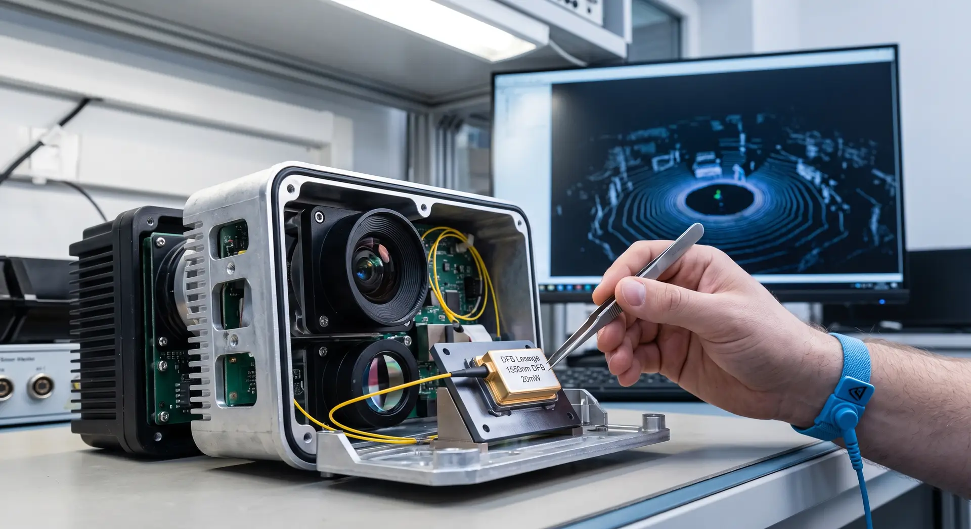
6. Matching DFB Laser Applications to Specifications
Different industries prioritize different metrics when selecting a single frequency laser diode. Understanding how to align your specific use case with the DFB laser data sheet is the hallmark of effective systems engineering.
- Telecommunications (DWDM Networks): The primary concerns are center wavelength accuracy, extremely high SMSR, and compatibility with standard ITU grids. Systems engineers will look for a DFB laser packaged in a thermally stabilized butterfly housing with low RIN, precise temperature tuning capabilities, and a diffraction grating for enhanced wavelength control.
- Gas Sensing (TDLAS): Tunable Diode Laser Absorption Spectroscopy requires a DFB laser that precisely matches the absorption line of the target gas (e.g., methane or carbon dioxide). Here, the wavelength tuning coefficients (both current and temperature) and narrow spectral linewidth are the most heavily scrutinized parameters on the data sheet.
- LiDAR and Optical Metrology: Automotive and industrial LiDAR systems require a DFB laser that offers high peak optical power, fast modulation capabilities, and a narrow linewidth to maintain a long coherence length for FMCW (Frequency-Modulated Continuous-Wave) radar applications.
Powering Next-Generation Systems with Inphenix
Interpreting a DFB laser data sheet is not just about reading numbers; it is about predicting how those optical, electrical, and thermal properties will interact within the broader ecosystem of your hardware. From managing thermal dissipation based on slope efficiency to mitigating dispersion penalties through SMSR and linewidth analysis, every parameter tells a story about system capability.
When your project demands uncompromising precision, reliability, and optical purity, the quality of the raw semiconductor material and the expertise in packaging make all the difference. As a vertically integrated manufacturer, Inphenix controls every step of the design and fabrication process.
Our world-class engineering team, renowned for its innovation, produces high-performance DFB lasers tailored for the most demanding telecommunications, medical, defense, and industrial sensing applications. Whether you require standard off-the-shelf ITU grid wavelengths, highly specific custom center wavelengths for gas sensing, or specialized custom laser packaging solutions to fit unique physical constraints, Inphenix delivers optical excellence engineered to your exact specifications.
Ready to integrate unparalleled optical performance into your next system design?
Explore our complete range of advanced lightsource solutions or reach out to our engineering team today to discuss how an Inphenix DFB laser can elevate your architecture, optimize your link budgets, and accelerate your time to market.